Solving Network Problems with Our All-In-One PROFIBUS Tester
We recently received a support call from one of the largest producers of carbon fiber. Part of this company’s carbon fiber production process included a programmable logic controller (PLC) that communicated over PROFIBUS with multiple devices. Within the last few months, however, the customer experienced a dramatic increase in PROFIBUS network faults — forcing the PLC into stop mode and jeopardizing overall product quality.
A conventional approach to diagnosing network problems is to use network monitoring tools and frame analyzers. However, in this case, these tools didn’t reveal any significant problems; everything looked just fine.
Measuring Signals Using Our PROFIBUS Tester 5
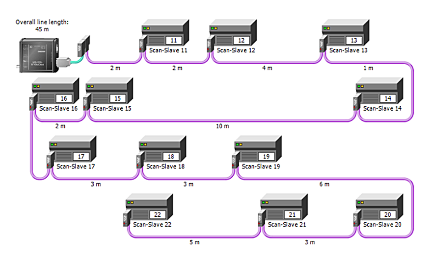
To figure out why the PLC was going into stop mode, we sent an experienced support engineer to the customer’s site. Since our customer had already checked the data using networking monitoring and frame analyzers, our engineer decided to analyze the electrical signal characteristics. Our engineer attached a PROFIBUS tester to the network to automatically determine the network topology and to analyze the signal quality for each active node on the network at multiple locations.
Next, our engineer performed a signal quality test, which is an overall composite of the signal tests that are required for proper PROFIBUS performance. The graph shows us a red horizontal line, which represents the minimal acceptable level of 2500. In this case, all the green bars — the PROFIBUS devices and nodes — are well above the line, which is good. The yellow bars, however, are below the line, which is not good. In fact, two devices, 13 and 14, are at zero.

The Built-In Oscilloscope Function Helps Locate the Signal Issues
While the green, yellow and red bars are the result of the tester’s signal-processing, our engineer wanted to look directly at the signal with the tester’s built-in oscilloscope function. The engineer connected the tester to the device with node address 22, which should yield a nice, rectangular signal within the oscilloscope view. Instead, the engineer saw a distorted signal that showed signal reflections in the cable trunk. Signal reflections are typically caused by bad connectors or missing bus terminations.

The oscilloscope display includes a cursor — note the blue vertical line in the image — that can be positioned freely on the display to measure the distance to the source of the reflection. After connecting the PROFIBUS tester at node 22, our engineer determined that the reflection occurred approximately 45 meters away from that node at the “other end” of the network adjacent to the PLC.
The first step was to check the PROFIBUS connector bus termination setting, which was correctly set to ON. Next, our engineer inspected the connector itself and found that the bus termination circuit within the connector was faulty. Replacing this PROFIBUS connector accomplished the following:
- It restored the correct bus-termination.
- The network’s signal quality returned to an acceptable level.
- We successfully eliminated the PROFIBUS network faults that were forcing the PLC into stop mode. Previously, the PLC couldn’t receive every data frame because the signal was too distorted.
For a complete picture of the health of your PROFIBUS network, it’s important to evaluate everything: the cables, connectors, topology, packets — and the signal itself. In this case, the PROFIBUS tester’s built-in oscilloscope function helped us locate the signal issues on the RS485 network.
To learn more, please consult the product page for our PROFIBUS Tester 5.
Softing Inc.
+1.865.251-5252